
Why EC
Permanent-magnet motor and integrated control for variable-speed duty.
Permanent-magnet motor and integrated control for variable-speed duty.
Comparing an EC (electronically commutated) PM synchronous motor with a fixed-frequency induction motor, the legacy site claimed "20% smaller, over 30% lighter than an induction motor of the same rating" — comparison figures with no reference model and no test condition, so they are not used here. Only three differences actually matter for ventilation equipment.
Three system differences for variable-speed ventilation
Qualitative, with no percentages. Each of the three is noticeable in how ventilation equipment actually runs, without instruments.
01Torque at low speed
Fixed-frequency induction
A fixed-frequency induction system does not provide continuous speed control. With a VFD it can maintain torque over a defined range, while continuous low-speed capability still depends on motor cooling, drive control and thermal limits.
EC
With suitable control, a PM synchronous system can cover low-speed operating points; the usable torque range still requires controller and thermal-limit data.
02Speed control
Fixed-frequency induction
A fixed-frequency scheme can only switch units on and off, leaving intermediate points unreachable; adding a VFD means another cabinet and more wiring.
EC
The controller sits on the motor; RS485 or a 0–10 V reference gives continuous speed control directly.
03System makeup
Fixed-frequency induction
Motor, drive and cabinet are three items, with a power cable run and a set of terminals between cabinet and machine.
EC
Motor and controller are one unit: one external wiring run and one separate cabinet fewer — which matters most where servicing is hard, such as roof units.
Actual operating limits require test data
T = 9550·P/n only converts one power–speed point into theoretical torque. The real torque–speed envelope also depends on continuous and peak current, voltage, control strategy and thermal limits; without them, the site shows one calculation point and no curve.
T = 9550 · P / n
The formula applies only to one paired operating point. Extremes from separate power and speed ranges cannot be combined; a real envelope requires controller limits, thermal limits and test data.
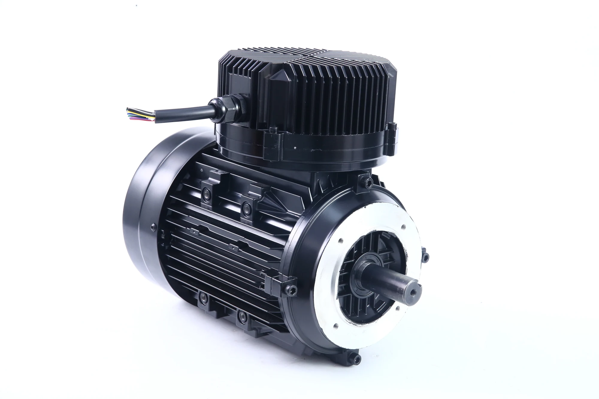
Controller and motor ship in one housing; the customer side needs only power and a single control signal. The RS485 register map and 0–10 V mapping are pending from the factory.
The third difference is drawn here too: controller and motor share one housing, so the customer-side interface is power plus one control signal. A fixed-frequency plus VFD scheme would add a cabinet node and a power cable run to this diagram.
Comparative data requires defined models and test conditions
Withdrawn is not the same as denied; the documents are missing. With a reference model, test conditions and a report, these can be said again — and said more firmly.
- D20% smaller than a PM motor of the same ratingNo reference model or measurement method, and the comparison object is a generic "other PM motors"
- DOver 30% lighter than an induction motor of the same ratingNo reference product model, structural dimensions or weighing condition
- DMeets IE5 efficiency classThe same sentence appears on all five versions with no test report locally
- D10–30% / 20–50% energy savingFrom legacy articles, with no verifiable project report or measurement baseline
Next
- T7Precision manufacturingBalancing / vacuum potting / finish machining / servo press/en/technology/manufacturing
- T2ProductsThree series, five versions side by side, plus the comparison table/en/products
- T5Livestock ventilationPrimary application, with the 58-inch four-point test table/en/applications/livestock