
01Front cover merged with the frame
- Reduces assembly steps
- Improves tolerance stack-up
- Eliminates the waterproofing failure risk of a mechanical joint
One joint fewer is one path for water fewer. It is also the first of the six steps to IP55 below.
Start from the application to define electromagnetic, thermal and structural limits.
Development starts from the application. Electromagnetic, mechanical and thermal simulation establish design limits, while integrated construction, interfaces and sealing define the assembly and protection path.
This page presents six structural protection measures recorded in the available material. Ratings such as IP55 are test conclusions and require a report identifying the models covered.
Two groups, six analyses. The electromagnetic set fixes the limits of torque and loss; the mechanical and thermal set fixes those of structure and heat. Both happen before any tooling is cut.
01Electromagnetic simulation
Sets torque ripple, iron loss and demagnetisation margin — whether torque holds at low speed is settled here.
02Mechanical & thermal simulation
Under negative-pressure duty the cooling airflow is falling away, so the control cover’s heat path has to be settled in simulation first.
The original simulation outputs are needed from the factory, each labelled with its analysis condition — speed, load, ambient — and the software version. A plot without its condition is decoration, not evidence.
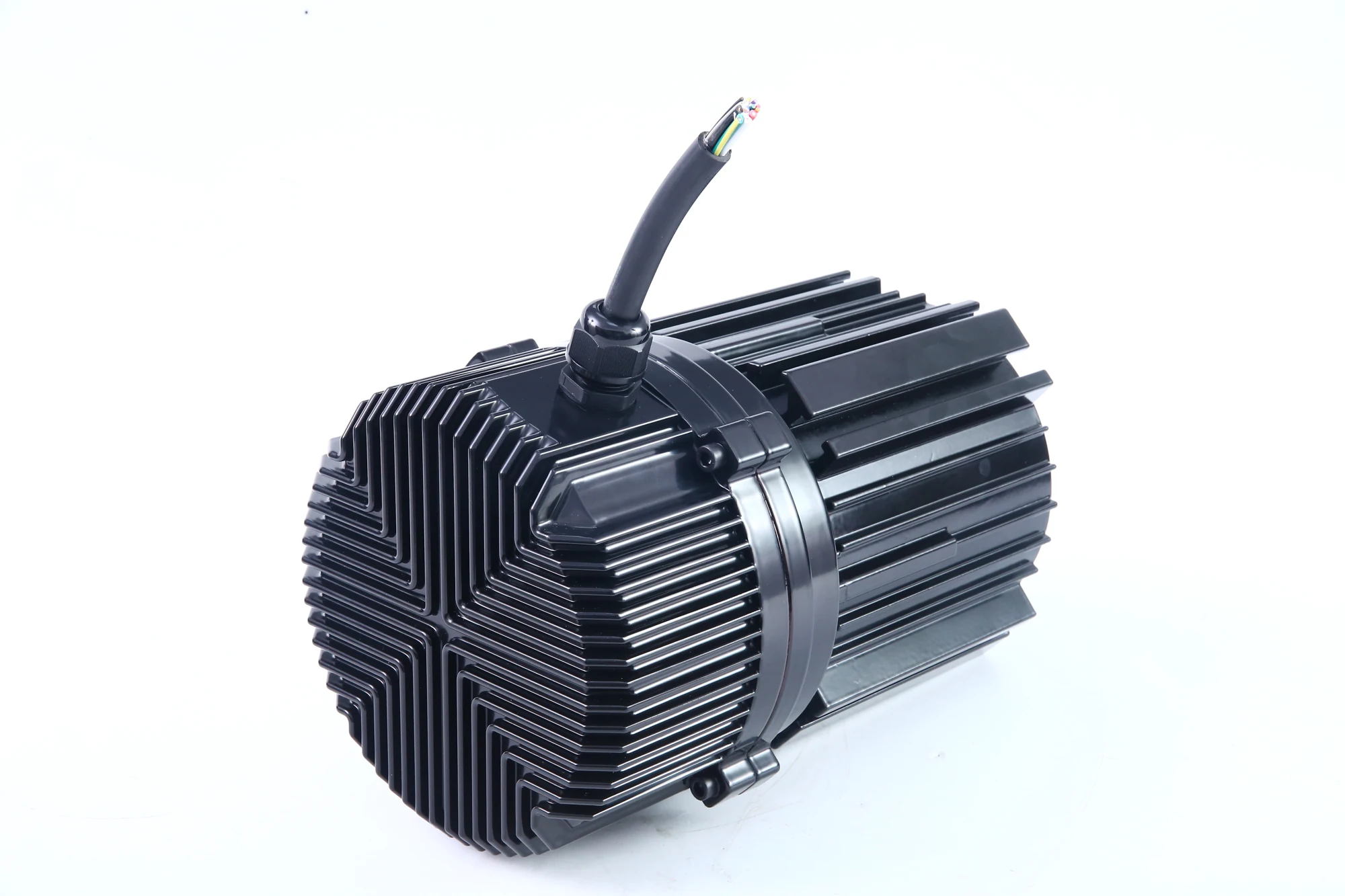
An integrated motor and controller reduce external connections and separate components. Structural design focuses on the housing, interfaces and sealing paths.
01Front cover merged with the frame
One joint fewer is one path for water fewer. It is also the first of the six steps to IP55 below.
02Sandwich structure of the rear cover
Overall length decides the mounting envelope. On roof units and in-duct direct drives, where space is tight, this is a selection threshold.
03Potting of the motor control
An integrated machine puts the controller on the motor, where it takes the motor’s vibration and temperature rise. Potting addresses both at once.
BSource: the product and development overview page of the standalone English site. That site has been unreachable since 2026-09-15; this is compiled from cache and the wording needs factory confirmation before publication.
The order runs outside in: first remove joints, then seal the joints that remain, and finally deal with the rotating parts. Each step closes the leak path the one before it cannot.
Six steps are not a report
These six are construction measures. They explain how protection is achieved; they are not an IP55 test report. Stating "IP55" as a product rating still requires an ingress-protection test report naming the versions covered.
Bhttps://rasta-motor.com/ec-motor-80-series/ (FAQ 6.8)
One section drawing explains all six steps far better than six lines of text. Either request a structural section from the factory, or draw a schematic from the engineering drawings once they arrive, labelled as schematic rather than as a drawing.
Documented construction details
Conclusions requiring test reports
Next